top of page
THE RECO-AIR PRODUCT RANGE

General Unit Construction


Reco-Air Units, as standard, are constructed with 25mm double skinned panels, galvanised steel finish internally and White Plastisol finish externally, providing a robust outer casing and ensuring good acoustic performance & thermal properties.

Where requested, the external appearance may be finished to comply with specific requirements.

Panels are insulated using 45 kg/m3 density mineral wool, with hinged / lift off access doors to the main filter sections and lockable black handles.


Reco-Air Units are configured to suit the particular application eg. ceiling suspended, floor mounted or roof mounted. Unit construction utilises 30-40mm Satin Anodised Aluminium pentapost framework with powder coated black adjustable support feet or base frame.

Prod1.png

Unit Classifications


Each Reco-Air unit is constructed to meet the following Eurovent (EN1886:2007) Classifications:


  • Air Leakage - Classification L2

  • External Panel Deflection - Classification D1


Specific Requirements


As a minimum requirement, each Reco-Air unit shall incorporate the following grade (or equivalent) filter media:
 

  • F1 - Grade G4 - Large grease particulate removal

  • F2 - Grade M6 – Fine grease particulate removal 

  • F3 - Grade E10 – Smoke, Steam & Moisture removal

  • F4 - Food Grade Activated Carbon cylinders –
    Odour removal
     minimum dwell time of 0.2 seconds


Please note: enhanced grades of filtration are available upon request.


All filter & fan doors shall incorporate a locking device, which can only be accessed by Authorised Personnel.

As a minimum requirement, each Reco-Air Unit shall incorporate the following fan assembly:


  • Fan section (EC Plug fan/fans) 230 V or 400 V (depending on unit capacity)

  • Single / Three phase, suitable for 0 to 10V signal control

  • Unit Duty to suit Current DW/172 Specific Extract Flow Rate (SEFR) & Project Specific Catering design requirements

  • Max. ambient working temperature to suit specific application

  • Each fan shall be Inverter Controlled - fan speed ramps up as the filter pressure increases to maintain a constant air volume flow rate at the cookline / canopy

 ​

Control & Interface Requirements


Reco-Air’s patented controls system protocol ensures the unit ceases to function if any of the following scenarios arise:


  • A unit filter access door is left open or ajar

  • Filters are removed or left out of the unit

  • The Building Fire Alarm system is activated

  • The registered pressure drop across any of the primary 3 sets of filters exceeds pre-set warning levels & reaches critical levels

  • The unit Isolator is turned Off

  • A system Timeclock - external controls - is not calling for system activation

  • A remote Shut-off safety feature - external controls - has been activated


When requested, an Interface system, which facilitates remote access & permanently monitors the filter pressure drops and enables adjustment of values, activity logging and emergency re-start, may be installed. This also provides access to Real Time filter status and ensures use of filters to full life.


As a standard feature, Electrical Cookline Interlock terminals are incorporated, which can be utilised to disable all essential cooking equipment whenever a ‘No Air Flow’ status is present.

This ensures no cooking operation can be effected without a proven & adequate air flow / extraction rate from the recirculation system / unit.


Air Commissioning / Testing


All Reco-Air units are fully commissioned and tested at the factory prior to being despatched.

On completion of any Reco-Air unit installation the air volume flow rates to extract & return air ductwork must be verified by a suitably qualified Air Commissioning engineer & a report produced as point of record. All test points must be sealed with proprietary plugs on completion of this operation.

The Reco-Air commissioned air flow rates and filter transducer / differential pressure set points shall also be recorded for future reference.


Reco-Air Unit Service & Maintenance


When planning the installation of the recirculation unit – however configured - adequate clearance must be allowed to facilitate safe Operative replacement of the filter media & fan(s).

To comply with our Standard Terms of Warranty – and Specific Landlord / Authority approvals – a Service Contract is required.  We recommend use of our Reco-Air accredited service partners.

Evidence of same must be made available prior to formal approval being acknowledged.


Reco-Air Unit Noise Breakout


In normal ‘Internal’ instances breakout noise from our Reco-Air unit will not exceed 60 dBA when measured at 1 metre (free field). Where Specific Authorities enforce lower noise levels, the Reco-Air unit construction can be modified accordingly.

Prod3.png
Reco DS.jpg
Prod2.png

For Reco-Air model dimensions & weights, and to discuss your specific needs, please contact us and we’ll be delighted to help.


CONTACT US

THE RECO-AIR TECHNICAL DATA
Reco-Air Technical table

Notes:


1. All Standard Models (S) available as floor mounted.

2. All Standard Models available for internal or external application.

3. UL – Underwriter’s Laboratories compliant.

4. DSI - Double Stacked Internal.

5. DSE – Double stacked External.

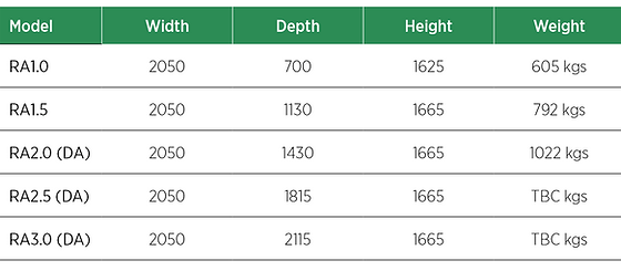
THE RECO-AIR DIMENSIONAL DATA
Floor Mounted units (See sample drawing here
Floor.PNG

Notes:


  1. All unit dimensions stated in millimetres.

  2. (DA) = Double Sided Access recommended – Access required front and rear of unit.

Void Mounted units (See sample drawing here)
Void.PNG

Notes:


  1. All unit dimensions stated in millimetres.

  2. (DA) = Double Sided Access recommended – Access required front and rear of unit.

Double Stacked units (See sample drawing here)
DS.PNG

Notes:


  1. All unit dimensions stated in millimetres.

  2. (DA) = Double Sided Access recommended – Access required front and rear of unit.

bottom of page